|
I was curious as to how simple I could make a clapper switch (a switch that activates from the sound of a loud hand clap) around an Arduino. By simple I mean the least possible amount of electronics for amplifying the microphone, etc. I would consider this as part of a larger project, maybe a robot that's controlled by hand claps. So here's the circuit I came up with: 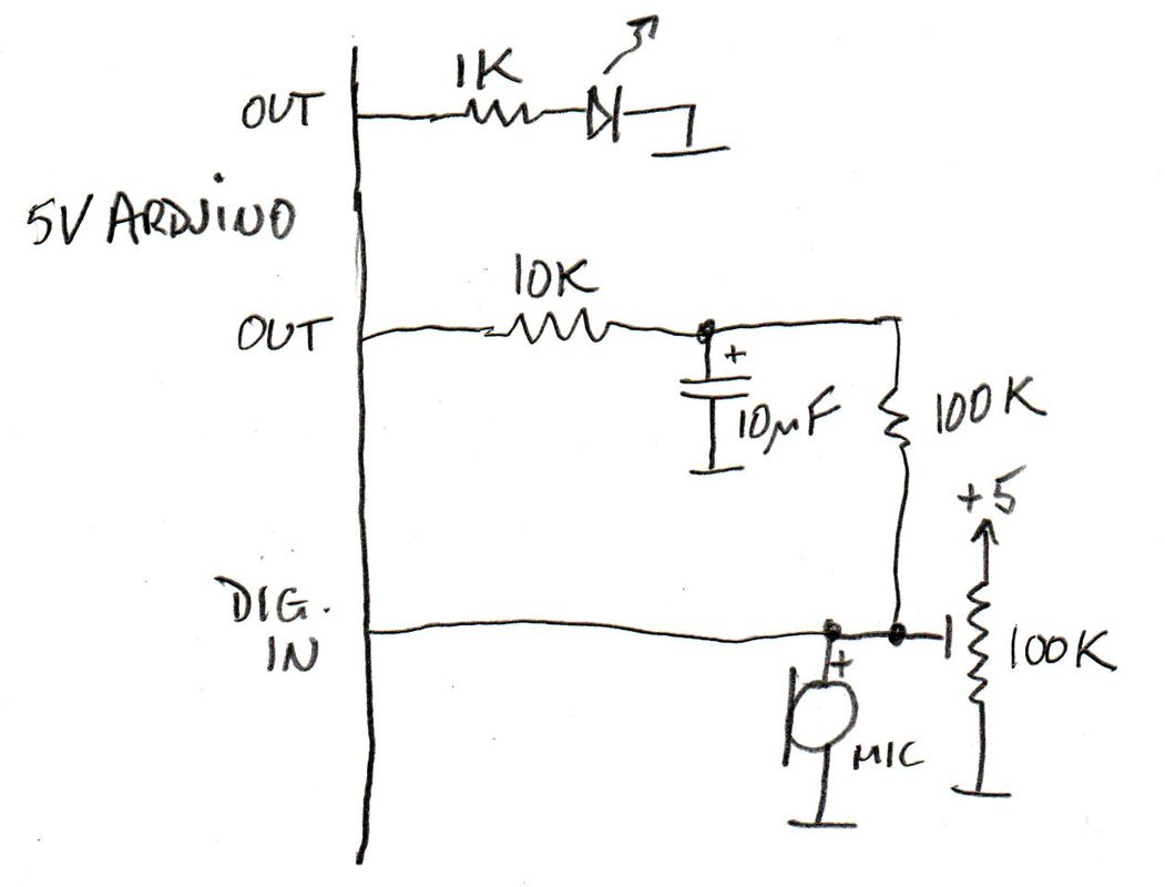 The microphone is an electret, bought dirt cheap off eBay. An electret microphone is a 2-pin device. You feed it power positive through a resistor and take off the sound from the junction between microphone and resistor. What I have done is to use a potentiometer instead. The pot is adjusted so the DC voltage out of the microphone is just on the input logic threshold of the Arduino. That means the Arduino input is very delicately balanced somewhere between logic high and logic low. Any voltage change generated by sound hitting the microphone will upset that balance. Now, it would be impossible to adjust the pot perfectly, and expect it to stay perfectly adjusted at the sweet spot. So what we do is to use a digital output to fine tune the setting. That's where the 10K and 100K resistors, and the capacitor come in. In the software, if the input is high the output is switched low, which will drive the input low again. When the input is low, the output is driven high to force the input back up again. Because the output can only ever be high or low, the system will forever chase its tail, and oscillate at a high frequency, in my case about 14kHz. That means it is switching state every 35 microseconds or so. However, if I make a loud sound by clapping my hands, the microphone will inject a transient voltage in the 100+ mV range. And because of the delay introduced by the capacitor, it will take some time for the system to catch up and cancel out the big change. While that is happening the oscillation stops. It's a fairly simple matter in software to detect that the input has not changed for X amount of time and hence register a clap. Because it takes quite a while for the system to settle back down, there has to also be a delay before it will re-arm itself to detect another clap. My code is below. I have the onboard LED just blinking to show it is alive (I like to have a heartbeat indication always). A task (a task in my terminology is a function that just gets called repeatedly from loop(). called AdjustBias() provides the closed loop feedback. ClapDetect() detects the clap by absence of input changes and sets a global boolean flag Clap. Finally Toggler() flips the state of the output LED (not to be confused with the Blinky/heartbeat one) on each clap. Footnote: In doing this I discovered that the Atmega328, and presumably other Atmel 8-bit processors, has hysteresis (backlash) on its input pins. Normally that would be a good thing, as it reduces noise sensitivity. In this case it threw me, because the scheme depends on hovering on the threshold. In my first attempt I didn't have the pot, and relied on the feedback to do all the work. The result was unstable. So I introduced the pot to do most of the heavy lifting and the feedback would only have to fine-tune, and it worked.
0 Comments
|
AuthorDavid Stonier-Gibson, retired EE. ArchivesCategories |
 RSS Feed
