An overview of different logic IC families
By David Stonier-Gibson
There are several different "families" of logic chip. Some are mutually compatible, others are not.
I am only going to cover those families you may encounter in everyday hobby use, so you can avoid mistakes that result in erratic behaviour in your inventions. It may also be that you want to repair some old equipment, and need to match a modern, available chip to an old, hard-to-get type.
When I talk about logic chips I mean chips containing functions like AND gates, decade counters, flipflops and the like. That excludes analogue chips like opamps or comparators, and microcontroller chips.
CMOS vs bipolar
The first thing you need to know is that two different technologies are in common use in logic chips. TTL, or Transistor-Transistor Logic is the oldest of the two, and uses bipolar NPN transistors. CMOS, or Complementary Metal Oxide Semiconductor, uses N-channel and P-channel MOSFETs. TTL is quite rare these days, but there is some still in use, and even sold at Jaycar. TTL is relatively power hungry and is limited to 5V operation. CMOS is by far the dominant type today, finding us in everything from logic chips (what this article is about) to the most powerful processor chips. There are versions of CMOS for voltages below 2V up to 18V or more. CMOS draws power in direct proportion to how fast it is being switched.
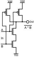
The two images below show the schematics for a two input NAND gate. TTL on the left, CMOS on the right.
The first thing you need to know is that two different technologies are in common use in logic chips. TTL, or Transistor-Transistor Logic is the oldest of the two, and uses bipolar NPN transistors. CMOS, or Complementary Metal Oxide Semiconductor, uses N-channel and P-channel MOSFETs. TTL is quite rare these days, but there is some still in use, and even sold at Jaycar. TTL is relatively power hungry and is limited to 5V operation. CMOS is by far the dominant type today, finding us in everything from logic chips (what this article is about) to the most powerful processor chips. There are versions of CMOS for voltages below 2V up to 18V or more. CMOS draws power in direct proportion to how fast it is being switched.
The two images below show the schematics for a two input NAND gate. TTL on the left, CMOS on the right.
|
|
74xx series logic
The first family of logic chips to really catch on was Texas Instruments 74 series TTL. These contain bipolar transistors, run on 5V, are fairly fast and use rather a lot of power. You don't see many straight 74 series chips any more, as more recent families have more to offer.
However, the 74xx numbering scheme has persisted. For example, a 7400 (seven-four-zero-zero) is a quad NAND gate. Today you can buy 74C00, 74HC00, 74HTC00, 74LS00, and 74S00. Those are 5V families. Then there are low (3.3V or lower) voltage families like 74LVC, 74AUP and so on and so on, almost ad infinitum. For some real 74-series porn see the Wikipedia page. I count 30 variations there! Some of these use bipolar transistors, others (these days most) use CMOS transistor technology.
So why is this a problem for a hobbyist? Not long ago I saw a SIG member mixing two different series on the one board, risking an unreliable outcome. If you understand a small number of the most crucial specifications for a family, you can easily work out if two chips of different families will work harmoniously with each other. You will also be able to exploit particular characteristics better.
Supply voltage range
The original 74xx family was specified to run off a supply voltage of 5V ±0.25V i.e. 4.75 to 5.25V. For several decades that was the norm for pretty much all logic chips, excepting early CMOS chips. The first CMOS chips, 74Cxx (and 4000 series, below) run off 5V to 15V, which opens up a lot of interesting possibilities. These days we have families designed for supply voltages less than 2V, and other families with similar type numbers that run off voltages up to 15V.
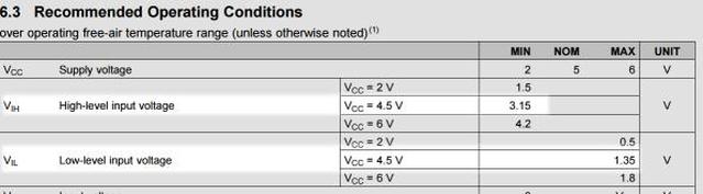
Input voltage levels
This is where it gets a bit interesting. Any logic chip will have a specified input low voltage and a specified input high voltage. These are usually listed as V(IL) and V(IH) in the data sheet. Don't confuse with maximum ratings - these are simply the voltages required for the chip to recognise the input as a low or high level (which you might think of as a logic zero or a logic one). In the table here I've highlighted the numbers for a single supply voltage (Vcc = 4.5V), to hopefully make it clearer. At Vcc=4.5V the input voltage must be more than V(IH) or 3.15V to be regarded as high. The input voltage must be less than 1.36V to be regarded as low. What this also implies is that if the input voltage lies between 1.35 and 3.15V all bets are off - you can't be sure what the chip will do. Hence anything driving this chip must have outputs that go above 3.15V for high or below 1.35V for low if you want to avoid trouble.
The first family of logic chips to really catch on was Texas Instruments 74 series TTL. These contain bipolar transistors, run on 5V, are fairly fast and use rather a lot of power. You don't see many straight 74 series chips any more, as more recent families have more to offer.
However, the 74xx numbering scheme has persisted. For example, a 7400 (seven-four-zero-zero) is a quad NAND gate. Today you can buy 74C00, 74HC00, 74HTC00, 74LS00, and 74S00. Those are 5V families. Then there are low (3.3V or lower) voltage families like 74LVC, 74AUP and so on and so on, almost ad infinitum. For some real 74-series porn see the Wikipedia page. I count 30 variations there! Some of these use bipolar transistors, others (these days most) use CMOS transistor technology.
So why is this a problem for a hobbyist? Not long ago I saw a SIG member mixing two different series on the one board, risking an unreliable outcome. If you understand a small number of the most crucial specifications for a family, you can easily work out if two chips of different families will work harmoniously with each other. You will also be able to exploit particular characteristics better.
Supply voltage range
The original 74xx family was specified to run off a supply voltage of 5V ±0.25V i.e. 4.75 to 5.25V. For several decades that was the norm for pretty much all logic chips, excepting early CMOS chips. The first CMOS chips, 74Cxx (and 4000 series, below) run off 5V to 15V, which opens up a lot of interesting possibilities. These days we have families designed for supply voltages less than 2V, and other families with similar type numbers that run off voltages up to 15V.
Input voltage levels
This is where it gets a bit interesting. Any logic chip will have a specified input low voltage and a specified input high voltage. These are usually listed as V(IL) and V(IH) in the data sheet. Don't confuse with maximum ratings - these are simply the voltages required for the chip to recognise the input as a low or high level (which you might think of as a logic zero or a logic one). In the table here I've highlighted the numbers for a single supply voltage (Vcc = 4.5V), to hopefully make it clearer. At Vcc=4.5V the input voltage must be more than V(IH) or 3.15V to be regarded as high. The input voltage must be less than 1.36V to be regarded as low. What this also implies is that if the input voltage lies between 1.35 and 3.15V all bets are off - you can't be sure what the chip will do. Hence anything driving this chip must have outputs that go above 3.15V for high or below 1.35V for low if you want to avoid trouble.
Interlude: Some terminology
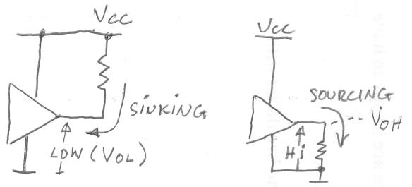
There's a special way of describing current flowing into or out of a pin.
There's a special way of describing current flowing into or out of a pin.
- If a pin is low, and has an external resistance to the positive supply rail, the current will be flowing into the pin. The pin is said to be sinking current.
- If a pin is high, and has an external resistance to the common supply (ground) rail, the current will be flowing out of the pin. The pin is said to be sourcing current.
Input currents
CMOS chips have very, very low currents at their input pins with normal voltage levels. The very worst case spec is 1µA, but it's very unlikely that would happen even at extreme temperatures. A more typical current is a thousandths of that, or 1nA.
Bipolar chips are a different matter. Standard 74 series TTL has a low input current of 1.6mA, which the driving chip must sink (it flows out of the pin towards ground). The high level input current is 40µA flowing into the pin. The table (left) shows the currents for standard 74-series TTL.
Output voltage levels
You might imagine that a logic chip running off 5V would have an output high voltage - V(OH) - of 5V and a low level - V(OL) - of 0V. NOT SO!
You might imagine that a logic chip running off 5V would have an output high voltage - V(OH) - of 5V and a low level - V(OL) - of 0V. NOT SO!
- For CMOS chips it is nearly true. But for bipolar chips it is far from true.
- For all chips the actual voltage depends on how much current is flowing in or out of the output pin.
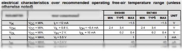
For bipolar, the output voltages are anything but "at rail", even with zero current. In fact, the high voltage will at best (no current) be at least 2 diode drops (~1.5V) below the Vcc pin. The low voltage will be maybe 0.2V, even with zero sink current (I say "maybe" because it's not specified in the data). The adjacent (left) table for bipolar 7400 shows output voltages when driving worst case ten 74-series inputs.
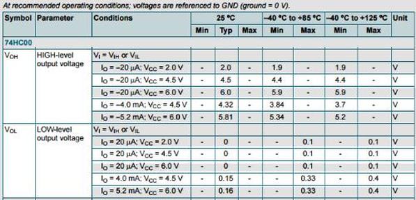
As I mentioned before, CMOS outputs will swing "rail to rail" with zero current loading, but if they are having to supply some current the voltage range will be reduced. The adjacent (right) table shows the output characteristic for 74C00, the most basic (and oldest) of CMOS gates. I have highlighted a single supply voltage to make it a bit more digestible. If you look at the 4mA figures you will see that more voltage is lost from the high output than from the low output. A lot of CMOS is like that; better at sinking than at sourcing, though many modern microcontroller chips are more symmetrical.
4000 series logic
4000 series is a family of CMOS chips that came out about the same time as 74Cxx. It runs off a wide voltage range, up to 15V. 45xx and 47xx part numbers are used for the more complex functions. Many 4xxx types have functional equivalents in 74xx, though there are often subtle differences. 74xx functions tend to be a bit more "conventional", like gates, counters, registers and buffers, while there are quite a few more "interesting" functions 4xxx, like analogue multiplexers, phase lock loops and very log (24-bit) counters. The wide voltage range technology used in 4xxx tends to make the slower than anything but basic 74Cxx.
4000 series is a family of CMOS chips that came out about the same time as 74Cxx. It runs off a wide voltage range, up to 15V. 45xx and 47xx part numbers are used for the more complex functions. Many 4xxx types have functional equivalents in 74xx, though there are often subtle differences. 74xx functions tend to be a bit more "conventional", like gates, counters, registers and buffers, while there are quite a few more "interesting" functions 4xxx, like analogue multiplexers, phase lock loops and very log (24-bit) counters. The wide voltage range technology used in 4xxx tends to make the slower than anything but basic 74Cxx.
If you want to go deeper into the topic, there's an excellent article here It is CMOS only. It has more history, descriptions of the internals of the chips and a number of useful circuit snippets.
